Combining Expansion Modules
Dieser Inhalt ist noch nicht in deiner Sprache verfügbar.
Every device on the Qwiic connector, the 100mil I2C extension header, and the onboard HDC1080 temperature/humidity sensor sits on the same I2C bus: bus_a, SDA on GPIO33, SCL on GPIO34, at 3.3V logic. For the physical pinout and connector location, see the Rev 3.x hardware page.
One shared bus means one clock speed, one address space, one set of pull-up resistors, and one power budget, all shared across whatever you plug in. Those are the four things that can collide when you combine more than one module, and they are the four sections below, after the compatibility matrix.
Compatibility matrix
Section titled “Compatibility matrix”| Device | Address | Max I2C speed | Typical current | Framework | Notes |
|---|---|---|---|---|---|
| HDC1080 (onboard) | 0x40 | 400 kHz | not measured | Any | Built into every board, always present, not a module you add |
| BME680 | 0x77 default, 0x76 via jumper | not verified | not measured | Any | |
| BME680 with BSEC2 | 0x77 default, 0x76 via jumper | not verified | not measured | Arduino only | Same chip and address as the plain BME680, so the two are mutually exclusive |
| SSD1306 OLED | 0x3C | 400 kHz | not measured | Any | |
| DS2484 | 0x18 | not verified | not measured | Any | I2C-to-1-Wire bridge for Dallas sensors |
| SCD41 | 0x62 (fixed) | 100 kHz (hard datasheet limit) | ~17 mA average at a 5s rate | Any | Heaviest current draw of the current module set, because of the NDIR cell |
No two devices in this table share an address: 0x40, 0x77 / 0x76, 0x3C, 0x18, and 0x62 are all distinct.
Bus speed: the slowest device wins
Section titled “Bus speed: the slowest device wins”One rule governs a shared I2C bus: the slowest device on it sets the ceiling for everyone. No module raises the bus speed on its own, so left alone the bus stays at ESPHome’s default of 50 kHz.
The one known collision on this board is the SCD41 against the OLED. The SCD41 has a hard 100 kHz limit, while the OLED page recommends 400 kHz for a smooth screen refresh. Run both together and the bus has to stay at 100 kHz or below, so the display simply refreshes slower. See Bus speed: the 100 kHz rule for the full explanation.
The hardware package defines bus_a as a list, which is what makes changing its speed from your own firmware config possible. Extend it with !extend, as the OLED module’s header comment shows:
i2c: - id: !extend bus_a frequency: 400kHzAddresses must be unique
Section titled “Addresses must be unique”No two devices on the bus may share an address. The onboard HDC1080 permanently occupies 0x40, so every module you add needs a different one. The current module set has no clashes, as shown in the matrix above.
To confirm your setup at boot, the bus runs with scan: true, so ESPHome logs every address it finds on every start. See the worked log example on the Qwiic overview page.
The BME680 case is worth calling out explicitly. The plain BME680 module and the BME680 with BSEC2 module drive the same physical chip at the same address, so they are mutually exclusive: importing both is a configuration error, not an address clash you can jumper your way out of. A second, separate BME680 chip alongside the first is possible, using the 0x76 solder jumper and the module’s bme680_address var.
Pull-ups add in parallel
Section titled “Pull-ups add in parallel”The board fits its own pull-up resistors, 4.7k on both SDA and SCL, on both the Qwiic connector and the 100mil extension port. That pair is already enough for the bus, and every Qwiic or STEMMA QT board you chain on adds its own pull-ups in parallel with it. SparkFun, who created the Qwiic standard, gives the rule that answers what to do about it: “As a general rule of thumb, disable all but one pair of pull-up resistors if multiple devices are connected to the bus.” On this controller, that one pair is the board’s own 4.7k, so the pull-ups to disable are the ones on the modules you attach, not the board’s.
Most breakouts make that easy to act on, though exactly how varies by board. SparkFun’s own Qwiic boards fit 2.2k pull-ups as standard, wired through a three-way jumper labeled I2C: cut it and the pull-ups disconnect. The Adafruit STEMMA QT spec does not commit to a resistor value at all; it only states the expectation that “the I2C device is expected to have pullups from SDA & SCL to V+”. Individual Adafruit boards still fit real resistors of their own choosing: the Adafruit Qwiic / STEMMA QT Breakout Board (#5961), for example, fits two 10k pull-ups that can be “deactivated by cutting some small traces on the back of the PCB, if they are not needed.” Check your own breakout’s documentation for its value and how to disable it.
Chaining pull-ups pulls in two opposite directions at once. More pull-ups in parallel lower the total resistance, which improves rise time but raises the current the bus has to sink. More devices and more cable raise the bus’s capacitance, which worsens rise time. Which one bites first depends entirely on what values the breakouts in your chain fit, which is why the rule of thumb above is the safe default rather than a module count.
As an illustration of that dependency, not a guarantee: against the board’s own 4.7k, breakouts fitting SparkFun’s 2.2k put you near 890 ohm with just two modules chained, already under the ~1k floor described below. Breakouts fitting the Adafruit board’s 10k instead leave you around 1.4k even with five modules chained, still comfortably above that floor, so capacitance would bite first there instead. The gap between those two real, sourced values is exactly why board-to-board pull-up values vary this much, and why disabling all but one pair beats trying to count modules.
Method 1: ohmmeter
Section titled “Method 1: ohmmeter”Power the board down before measuring.
- Measure resistance from SDA to
+3V3. - Unplugged, you should read the board’s own 4.7k.
- With the full chain attached, you read the parallel total of every pull-up on the bus.
The floor is roughly 1k. An I2C device only guarantees it can sink 3mA, and (3.3V - 0.4V) / 3mA works out to about 970 ohm. Below that, the bus can no longer pull the line down to a clean low level.
Method 2: oscilloscope
Section titled “Method 2: oscilloscope”Probe SDA at the far end of the chain, the worst case for both capacitance and pull-up strength. Trigger on a rising edge during real bus traffic, then measure the 30% to 70% rise time, which at 3.3V logic is 0.99V to 2.31V.
| Bus speed | Rise time budget |
|---|---|
| 100 kHz | under 1000ns |
| 400 kHz | under 300ns |
From the measured rise time you can back-calculate the bus capacitance: Cb is approximately tr / (0.85 x Rp). The I2C specification’s limit is 400pF.
No scope? Pass/fail only
Section titled “No scope? Pass/fail only”Without a scope, run the bus with your full chain attached and watch the ESPHome log for CRC errors and dropped readings. This is not a measurement, it is pass/fail. If the log stays clean, the chain works. If it does not, this failure mode looks identical to the SCD41 overclock symptom described above, so rule out the pull-ups before assuming a bad cable.
If a chain fails any of these three checks, disabling the extra pull-ups as described above, down to the controller’s one pair, is the fix all three point you toward.
The Qwiic cable sets the power budget
Section titled “The Qwiic cable sets the power budget”Everything on the bus, and every module powered from the Qwiic connector’s +3V3 pin, draws from the board’s 3.3V rail. But the rail is not what limits you here: the binding constraint is the Qwiic cable itself.
SparkFun, who designed the connector, states it plainly: “The very conservative max current on a Qwiic cable is 226mA. If you want to push it, 28AWG is good for up to 1.4A for chassis wiring.” This page adopts SparkFun’s conservative 226mA figure as the budget, rather than deriving its own.
The board’s 3.3V rail can spare more than 226mA under both conservative and best-case assumptions, so the board itself is not the bottleneck.
The status LEDs and the NeoPixel port run off the 5V rail, not the 3.3V regulator, so they do not eat into this budget either.
226mA against the SCD41’s ~17mA average, the heaviest module in the compatibility matrix above, is roughly 13 modules. Power is not the limit anyone will actually hit combining Qwiic modules on this board: addresses and bus speed bite first.
In practice this is irrelevant if the controller runs on USB or barrel-jack power, and only worth budgeting for if you are running something current-constrained, like a battery.
Everything at once: a five module medley
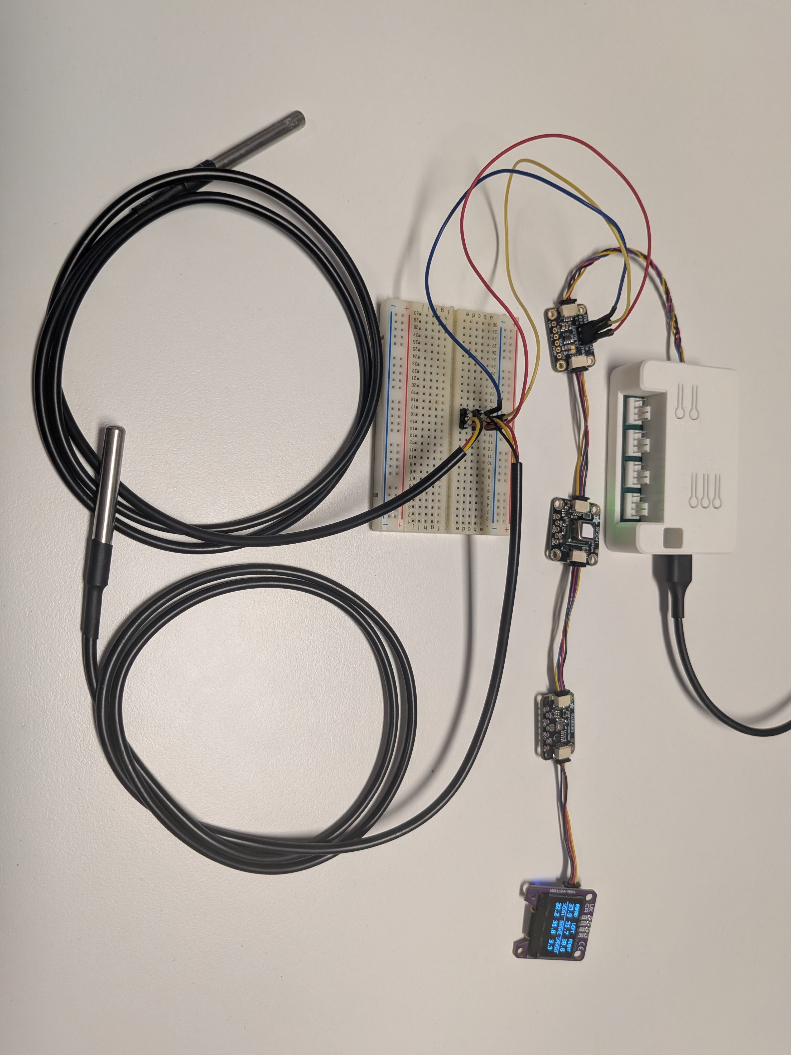
Section titled “Everything at once: a five module medley”The four rules above are easier to see in one config than in isolation. This one runs the OLED, the BME680, the SCD41, and the DS2484 with two DS18B20 sensors on it, all on the same bus, and puts every temperature the board can read onto the screen at once.
packages:  hardware:    url: https://github.com/zeroflow/wifi-fancontroller    ref: main    files: [hardware-rev-3.1.yaml]  oled:    url: https://github.com/zeroflow/wifi-fancontroller    ref: main    files:      - modules/oled_128x64.yaml  bme680:    url: https://github.com/zeroflow/wifi-fancontroller    ref: main    files:      - path: modules/bme680.yaml        vars:          bme680_name: "Intake"  scd41:    url: https://github.com/zeroflow/wifi-fancontroller    ref: main    files:      - modules/scd41.yaml  ds2484:    url: https://github.com/zeroflow/wifi-fancontroller    ref: main    files:      - modules/ds2484_onewire.yaml
# The SCD41 caps the shared bus at 100 kHz, so the OLED refreshes slower than# it would at its preferred 400 kHz. That is the tradeoff, not a fault.i2c:  - id: !extend bus_a    frequency: 100kHz
# Your own ROM addresses go here. Read them off the "1-Wire Devices" text# sensor after wiring the DS18B20s in. The ids are what the display needs.sensor:  - platform: dallas_temp    one_wire_id: ow_bus    address: 0xf23c01d607613d28    name: "Right Sensor"    id: t_right    update_interval: 30s  - platform: dallas_temp    one_wire_id: ow_bus    address: 0x273c01d607763628    name: "Left Sensor"    id: t_left    update_interval: 30s
# Replace the module's fan-RPM screen with a 3x2 temperature grid.display:  - id: !extend oled    lambda: |-      // Five temperatures in grid order. NAN means "not read yet".      float t[5] = {        id(fancontroller_temperature).state,   // onboard HDC1080        id(t_left).state,                      // DS18B20 via DS2484        id(t_right).state,                     // DS18B20 via DS2484        id(scd41_temperature).state,           // SCD41        id(bme680_temperature).state,          // BME680, named "Intake"      };
      // Sixth cell: how far apart the warmest and coldest sensor are.      float lo = NAN, hi = NAN;      for (float v : t) {        if (isnan(v)) continue;        if (isnan(lo) || v < lo) lo = v;        if (isnan(hi) || v > hi) hi = v;      }
      const char *labels[6] = {"BOARD", "LEFT", "RIGHT", "SCD41", "INTAKE", "SPREAD"};      float vals[6] = {t[0], t[1], t[2], t[3], t[4], isnan(lo) ? NAN : hi - lo};
      it.line(0, 30, 127, 30);
      for (int i = 0; i < 6; i++) {        int x = 21 + (i % 3) * 43;   // cell centres: 21, 64, 107        int y = (i / 3) * 32;        // row tops: 0, 32        it.print(x, y, id(oled_font_sm), TextAlign::TOP_CENTER, labels[i]);        if (isnan(vals[i]))          it.print(x, y + 13, id(oled_font_md), TextAlign::TOP_CENTER, "--");        else          it.printf(x, y + 13, id(oled_font_md), TextAlign::TOP_CENTER, "%.1f", vals[i]);      }
The photo above is that screen running: BOARD, LEFT and RIGHT across the top row, SCD41, INTAKE and SPREAD across the bottom. All six numbers are degrees Celsius, which is why no cell prints a unit: at 43px per column there is no room for one, and the label already says which sensor it is.
The sixth cell is the one worth stealing. Rather than showing a sixth sensor, it shows the spread between the warmest and coldest reading of the other five. That single number is what actually tells you whether the fans are keeping up, since a rising spread means heat is building somewhere faster than it is being moved, and it responds long before any individual reading looks alarming. Swap it for id(scd41_co2).state if a CO2 readout is more useful to you, or for id(bme680_gas_resistance).state if you want the VOC trend.
How the override works
Section titled “How the override works”The OLED module ships a fan-RPM screen. It is a top-level id, so !extend oled reaches it through the github:// package and replaces the lambda key wholesale, leaving the display’s platform, address, and update interval as the module defined them. The two fonts the module declares, oled_font_sm (6x12) and oled_font_md (8x16), stay available to your lambda. Both glyph sets already cover the uppercase labels and digits used above.
The layout is arithmetic rather than hand-placed: i % 3 picks the column and i / 3 picks the row, so the grid geometry lives in two expressions instead of twelve hardcoded coordinates. Adding a seventh reading means extending the arrays, not moving pixels.
Applying the four rules
Section titled “Applying the four rules”Every rule on this page shows up in that config:
| Rule | How this config resolves it |
|---|---|
| Bus speed | The SCD41’s 100 kHz limit beats the OLED’s 400 kHz preference, so the bus runs at 100 kHz and the display refreshes slower |
| Addresses | 0x40, 0x77, 0x62, 0x3C, 0x18, all distinct. The DS18B20s are 1-Wire ROM addresses behind the DS2484, not I2C addresses, so they do not enter the I2C address space at all |
| Pull-ups | Four breakouts chained is where the rule of thumb starts to matter, and this bench ran with all of them still fitted. See the note below before copying that |
| Power | Four modules against a 226mA budget is not close to the limit |