Qwiic / STEMMA QT Expansion
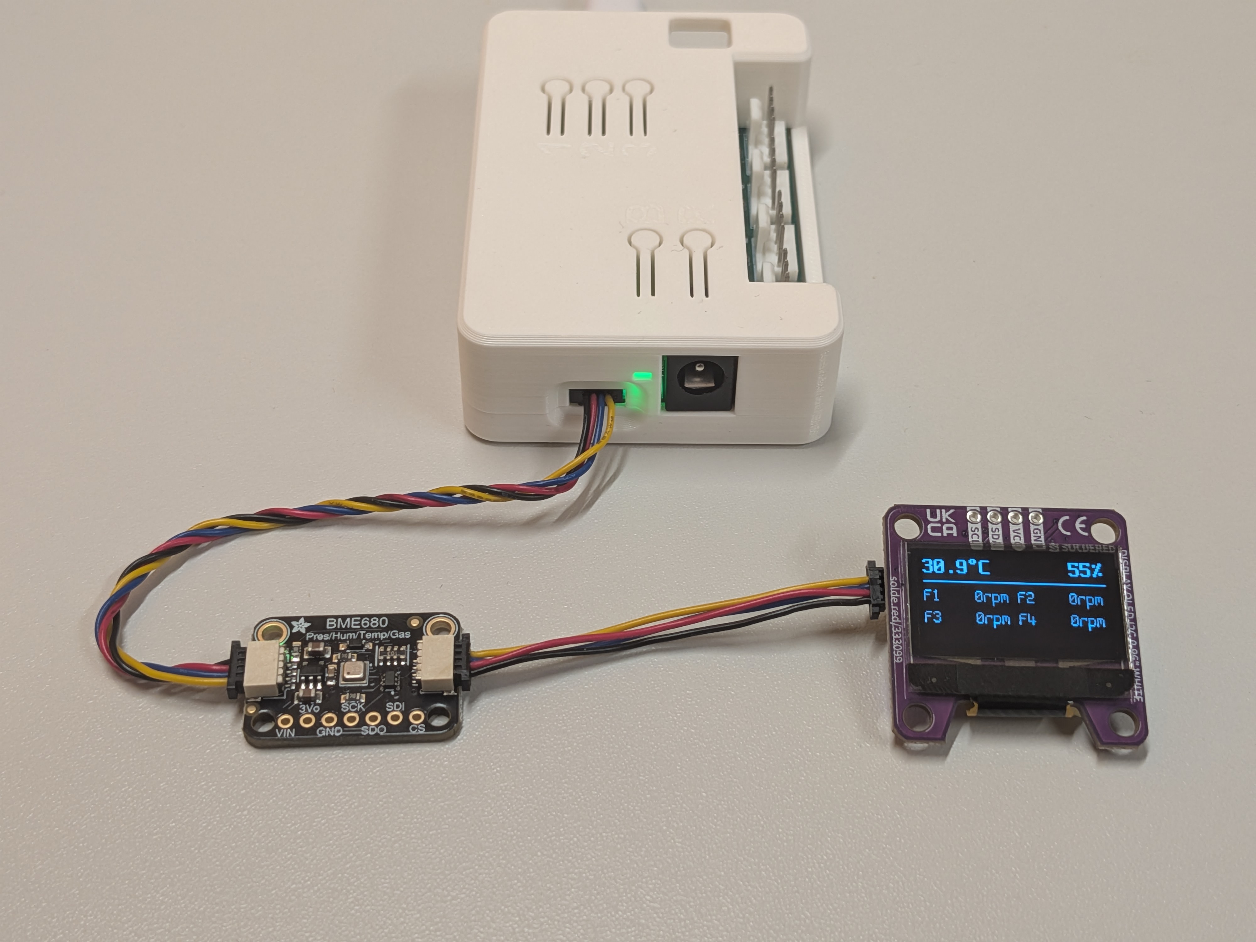
The Qwiic (also sold as STEMMA QT) connector is a solderless way to add I2C boards to the fan controller. Think environmental sensors, small OLED displays, RTCs, or GPIO expanders. Any I2C device that ESPHome supports can be wired in and exposed to Home Assistant without soldering.
The shared I2C bus
Section titled “The shared I2C bus”The Qwiic port, the 100mil I2C extension port, and the onboard HDC1080 temperature/humidity sensor all sit on the same I2C bus (bus_a, GPIO33 SDA / GPIO34 SCL), running at 3.3V logic.
The most important consequence: every device address on the bus must be unique. The onboard HDC1080 occupies 0x40, so any module you add must use a different address.
Finding a module’s address
Section titled “Finding a module’s address”The bus is configured with scan: true, so on every boot ESPHome logs each address it finds. This is the quickest way to confirm your new module is wired correctly and does not clash with the HDC1080:
[I][i2c:093]: Results from i2c bus scan:[I][i2c:099]: Found i2c device at address 0x40 # onboard HDC1080[I][i2c:099]: Found i2c device at address 0x77 # your new module (BME280)If your module shows up at 0x40, it conflicts with the onboard sensor. Most boards let you change the address with a solder jumper or a config option.
Adding a module
Section titled “Adding a module”You extend your own firmware YAML (the file that includes the hardware package), not the hardware package itself. Add the component under the matching platform (sensor:, display:, …) and point it at the existing bus with i2c_id: bus_a.
Here is a complete BME280 environmental sensor as a copy-paste starting point:
sensor: - platform: bme280_i2c i2c_id: bus_a address: 0x77 # default; 0x76 selectable on most boards temperature: name: "BME280 Temperature" humidity: name: "BME280 Humidity" pressure: name: "BME280 Pressure"That is the whole pattern. Any I2C device ESPHome supports drops in the same way: pick the right platform from the ESPHome component index, give it a free address, and reference i2c_id: bus_a.
Tested modules
Section titled “Tested modules”These boards have been verified on the controller and have their own worked examples, including any framework or library caveats:
- BME680: temperature, humidity, pressure, gas
- BME680 with BSEC2: BME680 with the Bosch BSEC2 air-quality library
- SSD1306 OLED Display: SSD1306 monochrome display
- DS2484: I2C-to-1-Wire bridge for Dallas sensors
- SCD41: CO2, temperature, humidity
Running more than one module
Section titled “Running more than one module”Multiple boards on the shared bus bring extra considerations: a single bus runs at a single clock speed (and not every device tolerates the same speed), pull-up resistors add up in parallel, and the 3.3V rail has a current budget. See Combining Expansion Modules for the details and a compatibility matrix.