Datasheet Rev 3.3
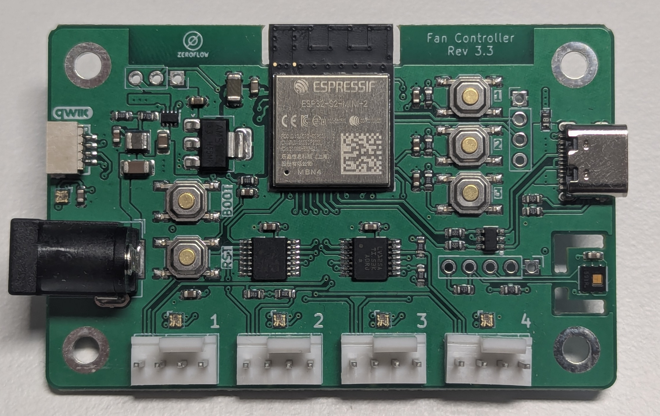
WiFi Fan Controller, hardware revision 3.3. A CE marked ESP32-S2 board that drives up to four 4-pin PWM fans, reads their tachometer signal, measures ambient temperature and humidity, and integrates natively with Home Assistant through ESPHome.
Rev 3.1, 3.2 and 3.3 are electrically compatible and share this specification. Sub-revision differences are manufacturing improvements only.
Key features
Section titled “Key features”- 4 independent 25 kHz PWM fan outputs with signal buffering
- 4 independent tachometer inputs, reported as RPM
- Onboard HDC1080 temperature and humidity sensor
- 5 addressable RGB status LEDs: one board status, one per fan connector
- WiFi 2.4 GHz, native Home Assistant integration via ESPHome
- Qwiic and 100 mil I2C expansion, NeoPixel output, SMD expansion header
- USB-C flashing, plus a UART0 serial header as fallback
- 3 user assignable push buttons
Absolute limits and electrical specifications
Section titled “Absolute limits and electrical specifications”| Parameter | Min | Typ | Max | Unit | Notes |
|---|---|---|---|---|---|
| DC input voltage | 11.4 | 12 | 12.6 | V | 12 V DC ±5 %, SELV, regulated SMPS only |
| DC input voltage, never to be exceeded | 15 | V | Including no load and light load | ||
| Total input current | 2.5 | A | Set by the DC barrel jack | ||
| Board electronics current, fans excluded | 50 | mA | |||
| PWM output frequency | 25 | kHz | Per fan, independently controllable | ||
| PWM duty resolution | 100 | steps | ESPHome speed_count: 100 | ||
| Logic level, all headers | 3.3 | V | Not 5 V tolerant | ||
| NeoPixel port voltage | 5 | V | |||
| NeoPixel port current | 2 | A |
The 2.5 A figure is the maximum total input current of the board. It applies to the sum of all connected fans plus the board electronics. Size the supply to the combined draw of the fans you connect, with headroom. See Safety and Compliance for the normative wording and for the full external power supply requirements.
The USB-C port powers the microcontroller only. It cannot power fans.
Operating and storage conditions
Section titled “Operating and storage conditions”| Parameter | Value | Reference |
|---|---|---|
| Climatic class | 3K3 | IEC 60721-3-3, weather protected indoor location |
| Ambient operating temperature | +5 to +40 °C | Bound of class 3K3 |
| Relative humidity | 5 to 85 %, non-condensing | Bound of class 3K3 |
| Pollution degree | 2 | IEC 62368-1 |
| Operating altitude | up to 2000 m | IEC 62368-1 |
| Ingress protection | none, bare PCB | An enclosure is required, see below |
| Installation | dry indoor locations only |
Operation without an enclosure is an excluded application. The board is supplied as a bare printed circuit assembly and must be installed inside a protective enclosure.
Mechanical specifications
Section titled “Mechanical specifications”| Parameter | Value |
|---|---|
| PCB outline | 70.0 x 45.0 mm |
| PCB thickness | 1.6 mm |
| Mounting holes | 4x, 3.2 mm diameter |
| Mounting hole pattern | 60.0 x 35.0 mm rectangle, symmetric about the board centre |
| Mounting hole inset from edge | 5.0 mm on all four sides |
| Maximum component height above PCB | 11.0 mm |
| Maximum component height below PCB | 2.5 mm |
| Overall envelope | 70.0 x 45.0 x 15.1 mm |
| Weight | 17 g board, 56 g board with case |
A STEP model of the assembled board is available in the hardware/
directory of the repository, for enclosure design and mounting clearance checks.
Processing and wireless
Section titled “Processing and wireless”| Parameter | Value |
|---|---|
| Module | ESP32-S2-MINI-2 |
| Core | Xtensa LX7, single core, up to 240 MHz |
| Flash | 4 MB |
| Antenna | integrated PCB antenna on the module |
| WiFi | 802.11 b/g/n, 2.4 GHz |
| Bluetooth | not available on ESP32-S2 |
| ESPHome board target | esp32-s2-saola-1 |
| Framework | arduino |
The arduino framework is required: the NeoPixel output on GPIO42 uses the
esp32_rmt_led_strip platform, which does not work reliably with esp-idf on the ESP32-S2.
Sensors and indicators
Section titled “Sensors and indicators”| Item | Specification |
|---|---|
| Temperature and humidity sensor | HDC1080, on the shared I2C bus |
| Default sensor update interval | 10 s |
| Tachometer input | pulse counter with internal pull-up, 2 pulses per revolution |
| Default RPM update interval | 1 s |
| Status LEDs | 5x SK6805 addressable RGB on GPIO1, WS2812 protocol, GRB order |
| LED assignment | LED 0 board status, LEDs 1 to 4 fan 1 to fan 4 |
Connectors
Section titled “Connectors”| Connector | Type | Notes |
|---|---|---|
| DC input | barrel jack 5.5 x 2.1 mm, centre positive | 12 V DC, external supply not included |
| USB-C | USB 2.0 device | Flashing and logs, powers the MCU only |
| Fan 1 to 4 | 4-pin fan header, 2.54 mm pitch | Standard 4-wire PWM fans |
| I2C expansion | 5-pin, 100 mil pitch | GND, INT, SCL, SDA, +3V3 |
| Qwiic / STEMMA QT | JST-SH 4-pin, 1 mm pitch | Shares the I2C bus |
| NeoPixel | 3-pin | 5 V, 2 A maximum, GPIO42 |
| Serial | 4-pin | 3V3, TX, RX, GND, UART0 at 3.3 V logic |
| Expansion | SMD header, board bottom | GPIO2 to GPIO11 |
The Qwiic port, the 100 mil I2C port and the onboard HDC1080 are all on the same I2C bus (GPIO33 SDA, GPIO34 SCL, 4.7 k pull-ups). Addresses must not conflict across those ports.
Pin assignment
Section titled “Pin assignment”| Pin | Usage |
|---|---|
| GPIO0 | Boot button, push to enter flashing mode |
| GPIO1 | RGB status LEDs, SK6805, 5 LEDs |
| GPIO2 to GPIO11 | Expansion header, board bottom |
| GPIO12 | Fan 1 PWM |
| GPIO13 | Fan 2 PWM |
| GPIO14 | Fan 3 PWM |
| GPIO15 | Fan 4 PWM |
| GPIO16 | Fan 1 speed sense |
| GPIO17 | Fan 2 speed sense |
| GPIO18 | Fan 3 speed sense |
| GPIO21 | Fan 4 speed sense |
| GPIO26 | unused |
| GPIO33 | I2C SDA |
| GPIO34 | I2C SCL |
| GPIO35 | I2C INT |
| GPIO36 | USR3 button |
| GPIO37 | USR2 button |
| GPIO38 | USR1 button |
| GPIO42 | NeoPixel expansion port |
| GPIO43 | UART0 TX, serial header |
| GPIO44 | UART0 RX, serial header |
| GPIO45, GPIO46 | unused, strapping pins |
Firmware and integration
Section titled “Firmware and integration”| Item | Value |
|---|---|
| Firmware | ESPHome |
| Integration | Home Assistant, native API |
| Provisioning | Improv Serial, plus WiFi captive portal fallback |
| Updates | OTA via ESPHome, and HTTP update from the manifest below |
| Factory firmware | fancontroller-r3-3-esp32s2.factory.bin |
| Update manifest | https://fancontroller.arthofer.dev/firmware/fancontroller-r3-3.manifest.json |
Optional control modules for temperature curves, PID control, closed loop RPM regulation and LED behaviour are documented under Modules.
Compliance
Section titled “Compliance”| Item | Status |
|---|---|
| CE marking | yes |
| RoHS | compliant |
| RF exposure | maintain at least 20 cm separation between the antenna and any person |
| Radio | contains a 2.4 GHz radio transmitter |
Intended use
Section titled “Intended use”Supply from an external 12 V DC SELV power supply, operation in dry indoor locations only, connection of 4-pin PWM fans only, maximum total input current 2.5 A.
Excluded applications
Section titled “Excluded applications”The product is not suitable for and must not be used in safety critical applications, explosive atmospheres, medical applications, operation without an enclosure, unattended continuous operation without regular checks, or in vehicles.
Firmware notice
Section titled “Firmware notice”The board ships with factory tested firmware, and the declaration of conformity covers the product in that state. Custom ESPHome YAML, custom modules or third party firmware may affect CE conformity, depending on what the change alters.
Configurations that stay within the documented envelope, such as a changed device name, an added temperature curve or a control module from this repository, change neither the radio nor the electrical behaviour the assessment rests on. Changes that leave it, in particular altering radio parameters like transmit power, changing the PWM output frequency away from 25 kHz, or operating the outputs outside their specified limits, void CE conformity of the product as delivered. No general approval is given for modified firmware, and responsibility for a modified configuration rests with whoever operates it.
Warranty claims are void for damage attributable to such a change.
The full normative wording is on the Safety and Compliance page. Where this datasheet and that page differ, that page applies.
Ordering information
Section titled “Ordering information”| Item | Value |
|---|---|
| Product | ESP32 WiFi Fan Controller |
| Hardware revision | 3.3 |
| Scope of delivery | assembled board with factory firmware |
| Not included | 12 V DC power supply, fans, enclosure |
| Shop | Tindie |
| Documentation | fancontroller.arthofer.dev |
| Source and hardware files | github.com/zeroflow/wifi-fancontroller |