Rev 1.0
Dieser Inhalt ist noch nicht in deiner Sprache verfügbar.
The Rev 1.0 is the original WiFi Fan Controller design based on the ESP32-WROOM-32E. It features serial flashing via a dedicated header and includes two external input ports not found on later revisions.
Hardware Package Import
Section titled “Hardware Package Import”Add this to your ESPHome config to import the hardware package:
packages: hardware: url: https://github.com/zeroflow/wifi-fancontroller ref: main files: [hardware-rev-1.0.yaml]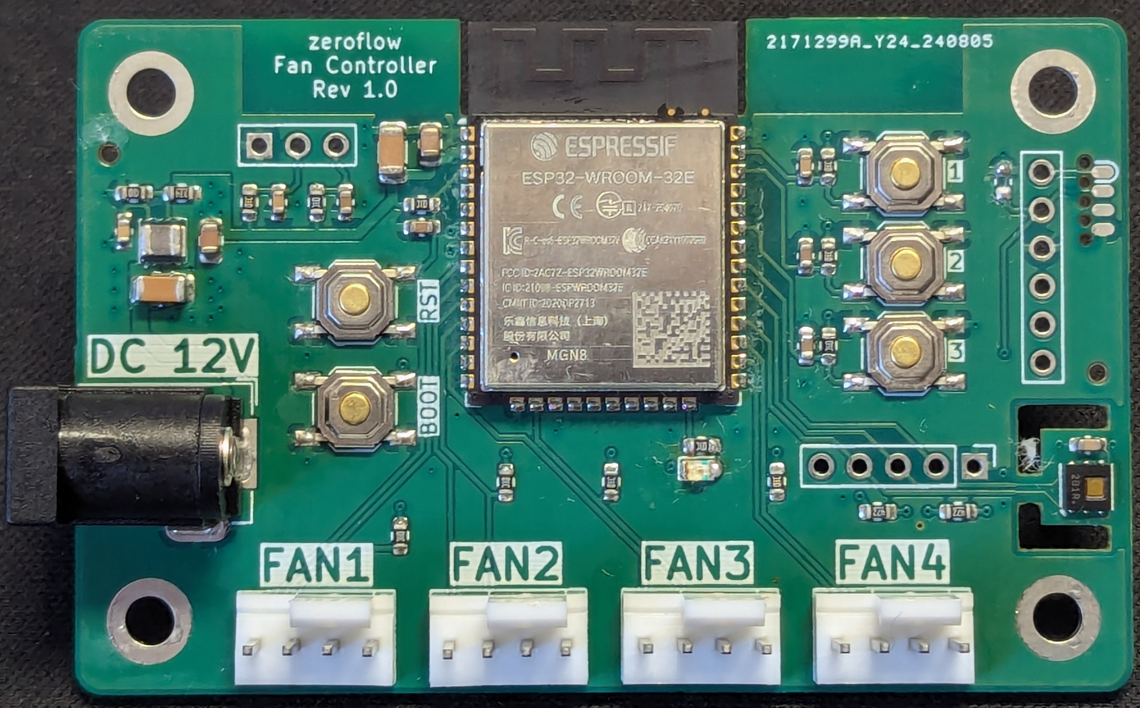
Specifications
Section titled “Specifications”- MCU: ESP32-WROOM-32E
- Board platform: esp32dev
- Power: DC Input (12V, 5.5x2.1mm)
- Max total input current: 2.5A (set by the DC barrel jack — applies to the sum of all fans plus board electronics, not per fan header; size your 12V PSU accordingly)
- Flashing: Serial header (100mil and SOCbite)
- Fan outputs: 4x PWM headers
- Status LED: Red (single)
- Sensor: HDC1080 Temperature and Humidity
- Buttons: Reset, Boot, 3x User
- Expansion: I2C port (100mil, SCL, SDA, INT), 2x external input (100mil)
Factory Firmware Installation
Section titled “Factory Firmware Installation”ESP32 Pin Assignment
Section titled “ESP32 Pin Assignment”| Pin | Usage |
|---|---|
| GPIO0 | Boot Button, Push to enter flashing mode |
| GPIO1 | Serial TX |
| GPIO2 | Builtin LED, Low=On |
| GPIO3 | Serial RX |
| GPIO4 | Fan 4 PWM |
| GPIO5 | Unused (strapping pin) |
| GPIO12 | Unused (strapping pin) |
| GPIO13 | Fan 3 Speed Sense |
| GPIO14 | Unused (outputs PWM at boot) |
| GPIO15 | Unused (outputs PWM at boot, strapping pin) |
| GPIO16 | Fan 4 Speed Sense |
| GPIO17 | I2C SDA (HDC1080 + expansion header) |
| GPIO18 | I2C SCL (HDC1080 + expansion header) |
| GPIO19 | I2C INT (expansion header) |
| GPIO21 | User Button 3 |
| GPIO22 | User Button 2 |
| GPIO23 | User Button 1 |
| GPIO25 | Fan 2 PWM |
| GPIO26 | Fan 2 Speed Sense |
| GPIO27 | Fan 3 PWM |
| GPIO32 | Fan 1 PWM |
| GPIO33 | Fan 1 Sense |
| GPIO34 | External Input 1 |
| GPIO35 | External Input 2 |
| GPIO36 | Unused |
| GPIO39 | Unused |
I2C Expansion Port
Section titled “I2C Expansion Port”The board offers an I2C extension port above Fan 4.
| Nr. | Pin | Description |
|---|---|---|
| 1 | GND | |
| 2 | INT | GPIO 19 |
| 3 | SCL | GPIO 18, 4.7k Pull-Up |
| 4 | SDA | GPIO 17, 4.7k Pull-Up |
| 5 | +3V3 |
External Input Port
Section titled “External Input Port”The board offers two external inputs, e.g. for a door intrusion alarm or a 100% power switch.
| Nr. | Pin | Description |
|---|---|---|
| 1 | GND | |
| 2 | IN2 | 10k Pull-Up |
| 3 | IN1 | 10k Pull-Up |
Example Configurations
Section titled “Example Configurations”- Basic Configuration — Minimal setup with 4 fans and essential features
For more examples, see the examples directory.