Rev 3.x (3.1 / 3.2 / 3.3)
Dieser Inhalt ist noch nicht in deiner Sprache verfügbar.
The Rev 3.x series is the latest generation of the WiFi Fan Controller. All 3.1, 3.2, and 3.3 boards share identical firmware and pinout — differences between sub-revisions are hardware-only improvements.
Key features over Rev 3.0: RGB status LEDs (SK6805) for board status and per-fan visual feedback.
Hardware Package Import
Section titled “Hardware Package Import”Add this to your ESPHome config to import the hardware package for your board revision:
packages: hardware: url: https://github.com/zeroflow/wifi-fancontroller ref: main files: [hardware-rev-3.3.yaml]packages: hardware: url: https://github.com/zeroflow/wifi-fancontroller ref: main files: [hardware-rev-3.2.yaml]packages: hardware: url: https://github.com/zeroflow/wifi-fancontroller ref: main files: [hardware-rev-3.1.yaml]Board Photos
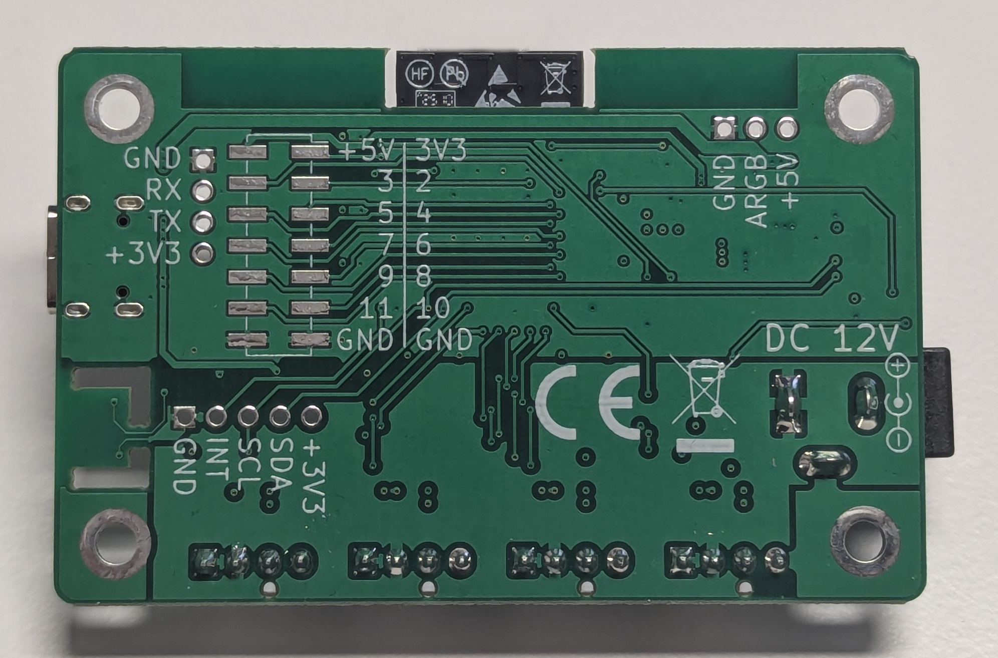
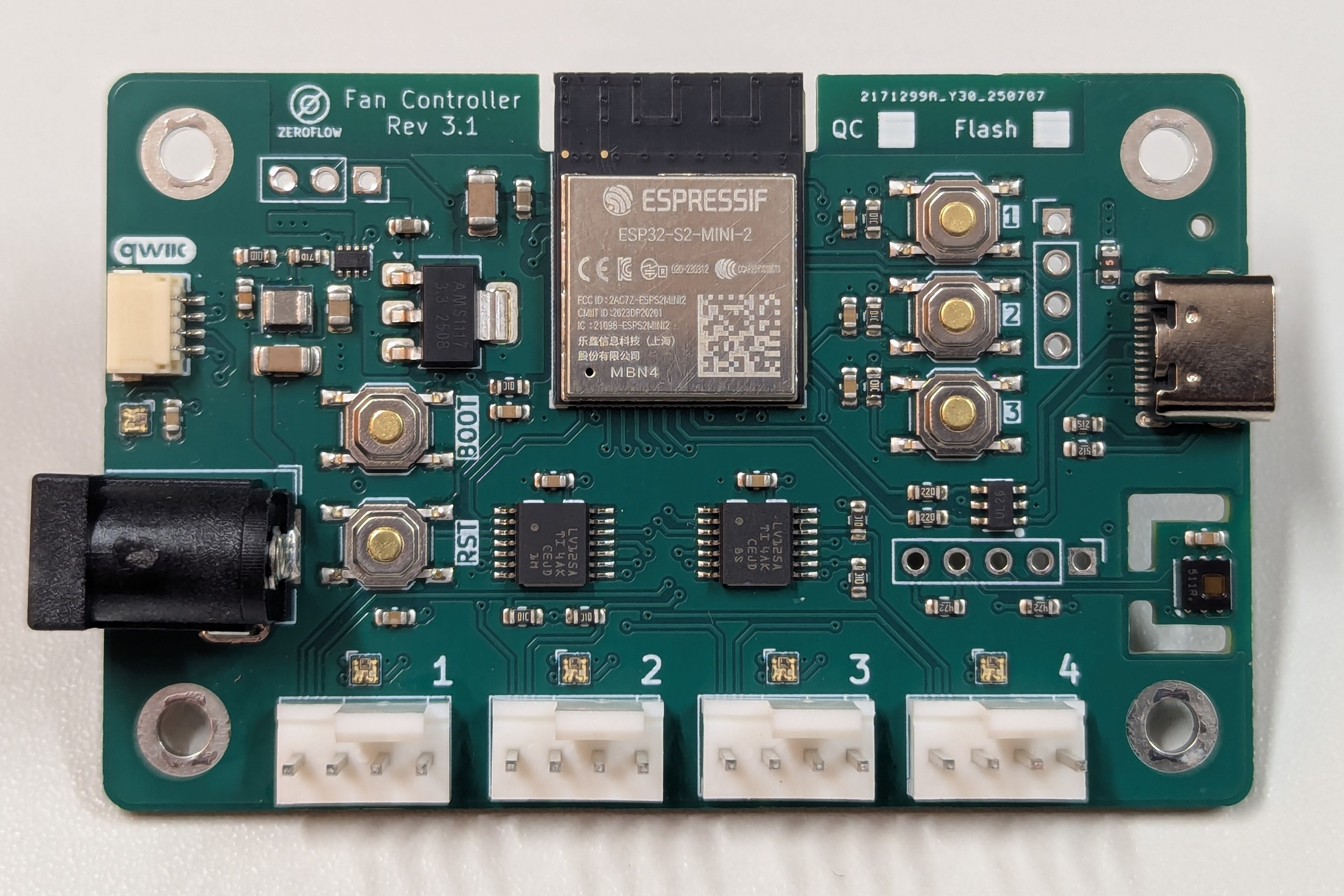
Section titled “Board Photos”Rev 3.3
Section titled “Rev 3.3”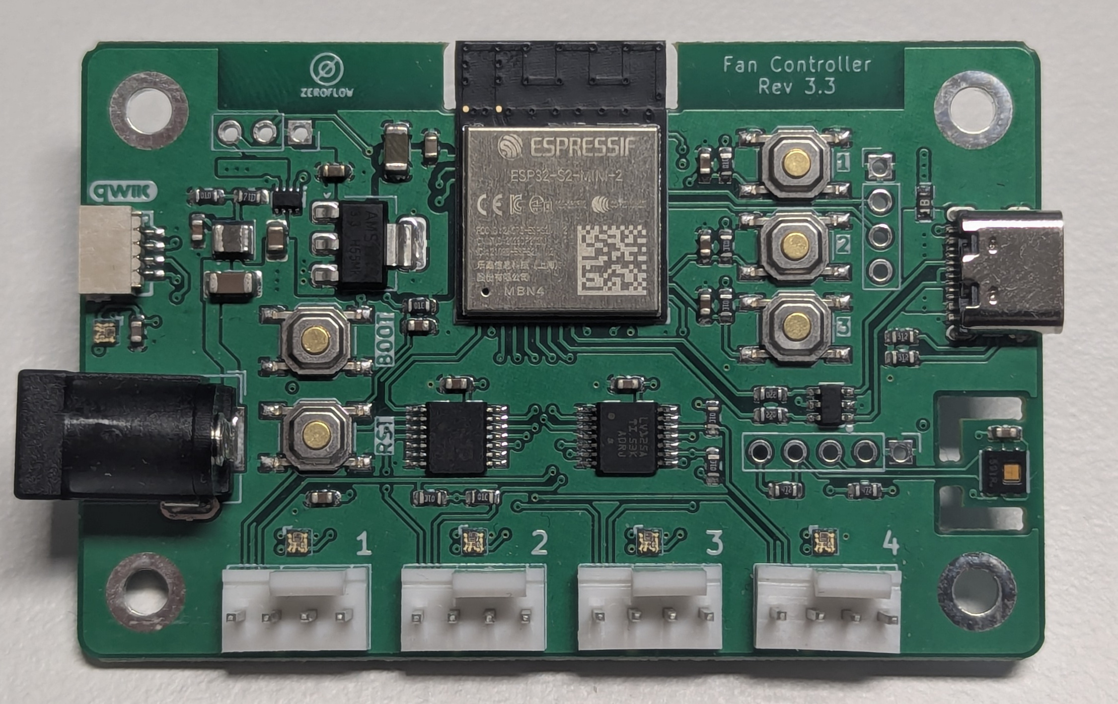
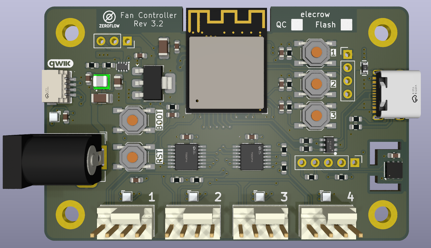
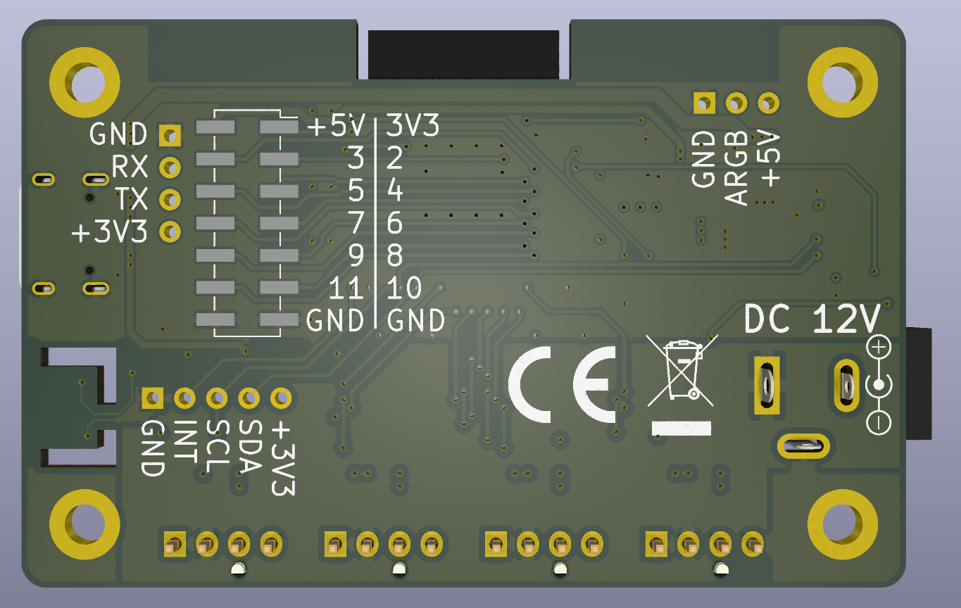
Rev 3.2
Rev 3.1
Specifications
Section titled “Specifications”- MCU: ESP32S2-Mini-2
- Board platform: esp32-s2-saola-1
- Power: DC Input (12V, 5.5x2.1mm)
- Max total input current: 2.5A (set by the DC barrel jack — applies to the sum of all fans plus board electronics, not per fan header; size your 12V PSU accordingly)
- Flashing: USB-C port
- Fan outputs: 4x PWM headers with signal buffering
- Status LEDs: SK6805 RGB LEDs for board status and each fan connector
- Sensor: HDC1080 Temperature and Humidity
- Buttons: Reset, Boot, 3x User
- Expansion: QWIIC I2C, I2C port (100mil), NeoPixel port (5V, max 2A), SMD expansion header
Factory Firmware Installation
Section titled “Factory Firmware Installation”Select your board revision and click the button to flash the factory firmware directly from your browser via USB.
ESP32-S2 Pin Assignment
Section titled “ESP32-S2 Pin Assignment”This pin table applies to all Rev 3.1, 3.2, and 3.3 boards.
| Pin | Usage |
|---|---|
| GPIO0 | Boot Button, Push to enter flashing mode |
| GPIO1 | RGB Status LEDs, SK6805 (5 LEDs, ESPHome uses WS2812 driver, GRB color order) |
| GPIO2 | Expansion Header (Bottom) |
| GPIO3 | Expansion Header (Bottom) |
| GPIO4 | Expansion Header (Bottom) |
| GPIO5 | Expansion Header (Bottom) |
| GPIO6 | Expansion Header (Bottom) |
| GPIO7 | Expansion Header (Bottom) |
| GPIO8 | Expansion Header (Bottom) |
| GPIO9 | Expansion Header (Bottom) |
| GPIO10 | Expansion Header (Bottom) |
| GPIO11 | Expansion Header (Bottom) |
| GPIO12 | Fan 1 PWM |
| GPIO13 | Fan 2 PWM |
| GPIO14 | Fan 3 PWM |
| GPIO15 | Fan 4 PWM |
| GPIO16 | Fan 1 Speed Sense |
| GPIO17 | Fan 2 Speed Sense |
| GPIO18 | Fan 3 Speed Sense |
| GPIO21 | Fan 4 Speed Sense |
| GPIO26 | unused |
| GPIO33 | I2C SDA |
| GPIO34 | I2C SCL |
| GPIO35 | I2C INT |
| GPIO36 | USR3 |
| GPIO37 | USR2 |
| GPIO38 | USR1 |
| GPIO42 | Neopixel Expansion Port |
| GPIO43 | UART0 TX (U0TXD), Serial Flashing Header |
| GPIO44 | UART0 RX (U0RXD), Serial Flashing Header |
| GPIO45 | unused (strapping) |
| GPIO46 | unused (strapping) |
Serial Flashing Header (TX/RX)
Section titled “Serial Flashing Header (TX/RX)”In addition to the USB-C port, the board exposes the ESP32-S2 UART0 on a serial header for flashing and serial logs. This is the fallback path when USB-C is not detected (see the USB troubleshooting note above) and the channel ESPHome’s logger uses by default.
| Signal | Pin | Description |
|---|---|---|
| 3.3V | 3.3V | |
| TX | GPIO43 | UART0 transmit (U0TXD), board to host |
| RX | GPIO44 | UART0 receive (U0RXD), host to board |
| GND | GND | Common ground (required for serial) |
Connect a 3.3V USB-to-serial adapter (TX to RX, RX to TX, GND to GND). To enter the bootloader for flashing, hold BOOT (GPIO0) while resetting the board.
I2C Extension Port
Section titled “I2C Extension Port”The board offers an I2C extension port above Fan 4.
| Nr. | Pin | Description |
|---|---|---|
| 1 | GND | |
| 2 | INT | GPIO 35 |
| 3 | SCL | GPIO 34, 4.7k Pull-Up |
| 4 | SDA | GPIO 33, 4.7k Pull-Up |
| 5 | +3V3 |
Qwiic Connector
Section titled “Qwiic Connector”The board offers a Qwiic connector (standard JST-SH 4-pin, 1mm pitch) for solderless I2C expansion. It shares the same I2C bus as the 100mil I2C extension port and the onboard HDC1080 sensor, so addresses must not conflict across both ports.
| Nr. | Pin | Description |
|---|---|---|
| 1 | GND | Black wire |
| 2 | +3V3 | Red wire |
| 3 | SDA | GPIO 33, blue wire, 4.7k Pull-Up |
| 4 | SCL | GPIO 34, yellow wire, 4.7k Pull-Up |
SMD Expansion Port
Section titled “SMD Expansion Port”The board offers an SMD expansion port on the back.
| Nr. | Pin | Description |
|---|---|---|
| 1 | +3V3 | |
| 2 | +5V | |
| 3 | I/O | GPIO02 |
| 4 | I/O | GPIO03 |
| 5 | I/O | GPIO04 |
| 6 | I/O | GPIO05 |
| 7 | I/O | GPIO06 |
| 8 | I/O | GPIO07 |
| 9 | I/O | GPIO08 |
| 10 | I/O | GPIO09 |
| 11 | I/O | GPIO10 |
| 12 | I/O | GPIO11 |
| 13 | GND | |
| 14 | GND |
Example Configurations
Section titled “Example Configurations”Basic Setup
Section titled “Basic Setup”- Rev 3.3 Basic — Minimal setup with 4 fans
- Rev 3.2 Basic — Minimal setup with 4 fans
- Rev 3.1 Basic — Minimal setup with 4 fans
Advanced Features
Section titled “Advanced Features”- RGB Status LEDs — Visual fan speed feedback with color-coded LEDs (red=slow, green=fast)
- RPM PI Control — Closed-loop RPM regulation per fan
- Temperature Control (Linear/PID) — Automatic fan speed adjustment based on temperature
- Temperature Curve — Flexible 5-point temperature curve with linear interpolation
For all available examples, see the examples directory.
Revision History
Section titled “Revision History”All Rev 3.1, 3.2, and 3.3 boards share identical firmware and pinout. The differences between sub-revisions are hardware-only improvements:
| Revision | Changes |
|---|---|
| Rev 3.1 | Added RGB status LEDs (SK6805) for board + per-fan indication |
| Rev 3.2 | Improved USB-C fuse for better overcurrent protection |
| Rev 3.3 | Open-drain fan outputs, optimized component selection, enhanced power supply stability |